
Recently, I seized the opportunity to recreate a 3D simulation program that I made during my University years. Back then, I didn’t know about versioning systems, and there was nothing like GitHub, so the code has been lost. But as I still remember how I implemented different parts of the program, I started the task, and put it on GitHub.
World object
The World object is the main program that takes care of the projection and the 3D objects visible in the viewport. My first version in early 2000 was using spherical projection, which means that the window you see, is actually a part of the surface on a sphere, with the observer in the center. But for the current version, I chose the projection surface to be a plane at a distance of f from the observer. This f is the focal distance of the projection.
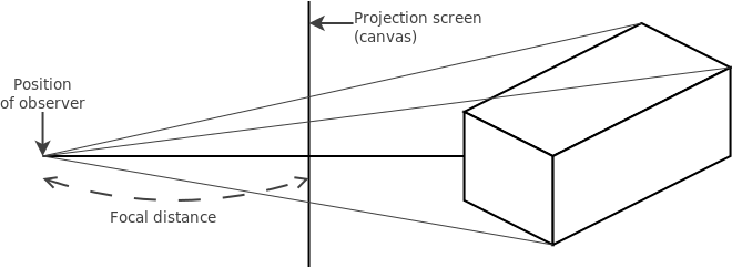
So using the rule of similar triangles, you can see that the projection coordinates (xp, yp) is derived from the 3D coordinates (x, y, z) as follows:

Placement and mesh
As every point in 3D space can be described as a vector, the placement vector of an object determines its position in 3D space. This is the center of the object, and this is also the point from where the object’s own coordinate system is based. Every object has its own X, Y and Z unit vectors, describing the coordinate axes of this object’s coordinate system. This information is stored in the BaseObject class.
public abstract class BaseObject {
    protected World w;
    protected Vector3d p;
    protected Vector3d[] axis;
}
The World instance is also stored within the object, so that it can calculate the projection coordinates of each of its mesh’s vertices, using the World‘s focal length. The Vector3d class comes from the javax.vecmath Java package, which is part of the Java3D API.
Each object has its own mesh of vertices, and internally, the coordinates of these vertices are stored with respect to the object’s own coordinate system. This allows us to:
- move the object by moving its center
- rotate the object around something by rotating its center around that point
- rotate the object itself by rotating its coordinate system’s axes around the object’s center
The mesh can be a bit complex, but to start with, I have implemented a Block class, which has a mesh of 8 vertices. These 8 vertices need to be connected in such a way that there are 6 rectangles to draw for its sides. These are the 6 polygons you’ll find back in the code.
A more general approach is to draw the surface of an object using triangles. The reason I want to use triangles, is to prevent having 4 or more vertices which do not lie in the same plane. For example, imagine bending a square over its diagonal. The 4 vertices of this “square” do not lie on a plane anymore, but instead it is composed of two triangles. The other reason is that I want to be able to calculate and store the normal vector of the surface, which is the vector perpendicular on its plane. A “bent square” has two planes, and therefore two normal vectors. This normal vector will be very useful in determining whether this part of the surface is visible to the observer or not.
Rotation
My initial implementation of rotation in 3D space was based on the fact that the rotation speed, being a vector, is the cross product of the rotation vector, and the radius of rotation:
The size of the rotation vector ω is interpreted as the rotation angle in radians, so basically the length of the arc of rotation, i.e. the length of the circle segment, would be:
This would then be the rotational displacement of the given point after 1 second. So my idea was to cut up this segment into smaller parts representing the rotational displacement of the given point for every frame, by using a certain FPS (frames per second) value in the World class. So I rescaled the displacement vector by dividing it by the World‘s FPS value, and then add this partial displacement, called delta, to the point being rotated. Finally, I need to make sure that the distance of this point from the point of rotation stays the same after the displacement, so I rescale the resulting point vector to be the same length as it was before. In Java code, this would be described as follows:


// base is the point around which I am rotating this.p
// omega is the rotation vector with which I am rotating this.p
public void rotate(Vector3d base, Vector3d omega) {
    Vector3d delta = new Vector3d();
    Vector3d p_base = new Vector3d();

    // Get the vector from base to this.p, and calculate delta from there
    p_base.sub(this.p, base);
    delta.cross(omega, p_base);
    delta.scale(1.0 / this.w.fps);

    // Add delta to p_base, and maintain the original length of the p_base vector
    double len = p_base.length();
    p_base.add(delta);
    p_base.scale(len / p_base.length());
    this.p.add(base, p_base);
}
You can find this code in the rotate functions of the BaseObject class at this point in the revision history.
This approach, rotation using vector mathematics, worked very well, until I noticed a slight skew when I let the object rotate for a long time. This skew was to be expected, as I am adding a straight delta displacement vector, and then rescaling the result vector to maintain the rotation distance. For high-precision animation, this is actually not done.
Well, enter quaternions.
Rotation using quaternions
What quaternions exactly are, is hard to visualize, but a quaternion is a set of four numbers, (w, x, y, z), so their vector space is four-dimensional. They have their own algebraic properties. These algebraic properties, somehow, make it easy for us to calculate new positions after a rotation. Why it works, I don’t know, but it works, and here is how.
Assume we have a vector in 3D space, (x, y, z). We turn this into a quaternion with w = 0. If we right-multiply this by a rotation quaternion q, and left-multiply this result by the conjugate of q, we get a new quaternion vector, of which the (x, y, z) triplet tells us something about the new position after rotation.
Magic, right?

First, let me clarify a few terms. We are right-multiplying and left-multiplying, to clarify how we do the multiplication. This is because quaternion multiplication is not commutative, meaning that given two quaternions p and q, the result of p·q is not the same as the result of q·p. Next, we have the conjugate of a quaternion. This is kind of like an inverse, and written as qT. The conjugate of the quaternion (w, x, y, z) is (w, -x, -y, -z). So just negate the (x, y, z) triplet.
So:

We are doing quaternion multiplication here, and the rules are a bit complex, and even complexer to understand why. Thankfully, the javax.vecmath package contains a class Quat4d for dealing with quaternions, and it has a mul function that does exactly the quaternion multiplication. As the multiplication is not commutative, you have to be careful what exactly it means to do a p.mul(q) and a r.mul(p, q). In the first case, it does p·q, and replaces p with this result. In the latter case, it does p·q and puts the result in r.
One more thing we need to do is to convert the rotation vector omega as we know it, with the angle of rotation in radians being exactly its vector length, into a rotation quaternion. Apparently, the rotation vector into rotation quaternion conversion is as follows:

In Java code, I’d have the following for converting omega into q:
double angle = omega.length() / 2.0;
double sin = Math.sin(angle);
double cos = Math.cos(angle);

Quat4d q1 = new Quat4d(
    omega.x * sin,
    omega.y * sin,
    omega.z * sin,
    cos
);
Note: in the constructor of Quat4d, w comes last!
I have called it q1 as I am going to have its conjugate q2. The rotation function then continues as follows:
// We need to normalize the rotation quaternion
q1.normalize();

Quat4d q2 = new Quat4d(q1);
q2.conjugate();

// Note: v is a Vector3d parameter to this function, being the vector
// we want to rotate around (0, 0, 0). So if we want to rotate a point p
// around some point q, v would be p - q

// Now we calculate the result of the multiplications
Quat4d rotated = new Quat4d();
Quat4d qv = new Quat4d(v.x, v.y, v.z, 0); // The quaternion version of v
rotated.mul(q2, qv);
rotated.mul(q1);

// We extract the (x, y, z) triplet from the result, and rescale it
// to the original vector v's size
Vector3d result = new Vector3d(rotated.x, rotated.y, rotated.z);
result.scale(v.length());
In my actual code, I am also dividing the rotation angle by this.w.fps to get the fraction of the angle needed for the current frame. And finally, I am actually also doing the following multiplication, but that should be the same as what was described before:

Check out the BaseObject::_rotate function on GitHub! Hope this post has been useful to someone!